
How-To Guides
How Do Engineers Build Underwater Constructions?

Imagine standing on a bridge that stretches across a vast river or driving through an underwater tunnel that connects two cities. Have you ever wondered how these massive structures are built beneath the water’s surface? Constructing underwater is one of the most complex engineering tasks. It requires special techniques, strong materials, and careful planning. Engineers build bridges, tunnels, oil rigs, and research stations beneath the water’s surface. But how do they do it? They must overcome strong water currents, high water pressure, and corrosion. Yet, these structures remain stable for decades. This article’ll explore the fascinating world of underwater construction and the advanced methods that make it all possible.
Why is it Important to study the environment of the underwater construction?
Before building underwater, engineers study the site carefully. They check the geology and environment to ensure safety and stability. The underwater world has many challenges. The seabed can be unpredictable. Strong currents can be dangerous. Construction can also affect marine life. Engineers must understand these factors. This helps them design strong and lasting structures.
One important step in underwater construction is surveying the seabed. Engineers analyze the terrain and composition of the ocean or riverbed. They use advanced technology, like ultrasonic sound navigation, to collect accurate data. This helps create detailed 3D maps of the underwater area. These maps show depth changes, obstacles, and weak spots. Studying the geology and environment before construction is crucial. It ensures the structure is built on a strong and stable foundation.
Methods that Engineers use to build Underwater constructions
Caissons
Caissons are essential structures in underwater construction, providing a dry working environment for engineers to build stable foundations beneath water bodies. These large, watertight enclosures are either sunk into the seabed or placed in position and sealed to allow workers to construct piers, bridge foundations, or other underwater structures.
Types of Caissons in Underwater Construction

wikimedia commons
Open Caissons
Open caissons are hollow, bottomless structures used for underwater excavation. They sink deeper as engineers remove soil from inside. These caissons are usually made of steel or reinforced concrete. They are ideal for areas with soft or unstable soil. During construction, the caisson is placed on the seabed. As soil is removed, it sinks due to its own weight. Engineers may add concrete or other weight to help it reach the right depth. Once in place, the caisson is filled with concrete. This creates a strong and stable foundation. Open caissons are used for bridge piers, docks, and marine structures. A famous example is the Brooklyn Bridge, which used open caissons for its underwater foundations.

Brooklyn Bridge – pixabay.com
Box Caissons
Box caissons are watertight structures with a closed bottom. They are built on land and floated to the site. Once in place, they are carefully sunk onto the seabed. Engineers fill them with concrete to create a strong foundation. No excavation is needed since they are sealed at the bottom. They work well in shallow to moderate waters. Box caissons are used for harbors, quay walls, breakwaters, and offshore platforms. Their pre-built design makes construction faster and safer.
Pneumatic Caissons
Pneumatic caissons are used for deep-water construction. Traditional open caissons cannot handle high water pressure. They look like open caissons but have an airtight chamber at the bottom. This chamber is filled with compressed air to keep water out. Workers enter the pressurized chamber to remove soil. This helps lower the caisson to the required depth. This method allows precise excavation in deep waters. It is used for large infrastructure projects.
Cofferdam

Cofferdam – wikimedia commons
A cofferdam is a temporary, watertight enclosure built in or around a body of water to create a dry work environment for construction. It allows engineers to build foundations, piers, and other structures below the waterline without the challenges of working underwater. Once the construction is complete, the cofferdam is removed, and the water is allowed to return to its natural state.
Types of Cofferdams
Earthen Cofferdams
Earthen cofferdams are made from soil, clay, or gravel. These materials are compacted to create a barrier that holds back water temporarily. They work best in shallow water. To reduce seepage, they are often reinforced with a waterproof membrane or sheet piles. Engineers use them for river diversions and dam repairs
Rockfill Cofferdams
Similar to earthen cofferdams, rockfill cofferdams use large rocks and stones to create a strong, water-resistant barrier. They are often used in fast-flowing rivers where water pressure is high, as the heavy rocks provide stability.
Cellular Cofferdams
Cellular cofferdams are used for large-scale projects where high water pressure and deep foundations are involved. They are made up of interconnected steel cells, filled with earth or gravel, to create a self-supporting barrier against water. Cellular cofferdams are commonly used in dam construction, harbor walls, and offshore structures.

cellular cofferdam – wikimedia commons
Underwater construction needs special equipment and advanced technology. Safety, precision, and efficiency are key. Engineers use heavy machinery, diving gear, and remote-operated systems. Dredgers remove sediments, rocks, and debris before construction. Modified excavators and backhoes assist in building. Diving equipment and underwater robots ensure safe and precise work. And also divers use surface-supplied air systems, helmets, and full-face masks for clear communication. Autonomous Underwater Vehicles (AUVs) scan the seabed and monitor conditions without human help.
Challengers in Underwater Construction
Underwater construction comes with many challenges, but engineers use advanced techniques to solve them. The deeper the construction, the more pressure there is, which stresses materials and equipment. Engineers use strong materials like reinforced concrete and special steel to withstand this pressure. Also corrosion is another issue. Water exposure can weaken structures. Therefore, Engineers use coatings, corrosion-resistant alloys, and cathodic protection systems to prevent this. Underwater construction can also harm marine life and ecosystems. To reduce the impact, engineers use eco-friendly methods. These include biodegradable materials, minimizing sediment disturbance, and creating artificial reefs. These solutions help make underwater structures durable, safe, and environmentally friendly.

photo credits – pexels.com
The future of underwater construction will change how we interact with the ocean. Projects like floating cities and deep-sea research stations are becoming real. These innovations will help solve problems like overpopulation, climate change, and scientific exploration. New technologies, including robotics, AI, and strong materials, are making underwater projects safer and more efficient. As engineering advances, underwater construction will expand human capabilities. It will also help protect the environment and marine ecosystems. In the future, we’ll see more eco-friendly, advanced underwater structures. These will unlock new possibilities beneath the ocean’s surface.


Engineering life is busy. There are lectures, labs, and endless assignments. But there is also a chance to earn money and build skills before graduation. This is where freelancing as an engineering student comes in. Freelancing gives you freedom. You can work from your dorm, your home, or even the campus library. You set your rates. And you decide your schedule. For engineering students, freelancing is more than extra cash. It is real-world experience. It helps you apply what you learn in class. Also, it builds your portfolio. And it can open doors to bigger opportunities after graduation. In this guide, I will share how to start freelancing as an engineering student. I’ll cover skills, platforms, portfolios, clients, and time management. Let’s begin.
Why Freelancing as an Engineering Student is a Smart Choice
Freelancing is flexible. You can work during semester breaks or weekends. No boss is telling you to work 9 to 5. You also get to choose projects that match your field. If you are studying electrical engineering, you can work on PCB design. If you are into mechanical engineering, you can do CAD modeling. This way, your work doubles as practice. Freelancing also teaches soft skills. You learn how to negotiate and learn how to meet deadlines. You learn how to communicate with clients. These are skills employers value. And yes, you earn money. Even a small project can pay more than a part-time campus job.
Step 1: Identify Your Skills
The first step to starting freelancing as an engineering student is knowing your skills.
You do not need to know everything. Focus on what you are good at. This could be:
• CAD design (SolidWorks, AutoCAD)
• PCB design (Altium, KiCAD)
• Programming (Python, MATLAB, C++)
• Data analysis
• Technical writing
• Simulation (ANSYS, Proteus)
Make a list of your skills. Then think of problems you can solve with them. For example, if you know MATLAB, you can offer data visualization services. If you feel your skills are basic, invest time in learning. Free courses on platforms like Coursera, edX, or YouTube can help.
Step 2: Build a Portfolio

image courtesy – pexels.com
Clients want proof. They want to see what you can do. Your portfolio is your proof. It shows your best work. If you do not have real projects yet, create sample ones. For example:
• Design a sample circuit and explain it in a PDF.
• Create a 3D model of a mechanical part.
• Write a technical blog post.
Keep your portfolio clean and simple. Use clear titles. Add short descriptions. Include images, code snippets, or diagrams.
You can host your portfolio on:
• GitHub (for coding projects)
• Behance or Dribbble (for designs)
• Personal website (using WordPress or Wix)
A good portfolio makes you look professional, even if you are still a student.
Step 3: Choose the Right Freelancing Platforms
There are many freelancing platforms. Each has its style. Some are general. Some focus on engineering.
Popular platforms for engineering students include:
• Upwork – Good for technical projects.
• Fiverr – Great for small services like CAD drawings or report writing.
• Freelancer.com – Has many engineering categories.
• Toptal – For advanced professionals (once you have experience).
• Workana – Popular in Asia and Latin America.
Join one or two platforms. Do not sign up everywhere at once. Learn how one platform works before trying others.
Step 4: Create a Strong Profile
Your freelancing profile is like your resume. Clients will read it before hiring you.
A good profile should have:
• A professional photo (clear, friendly, well-lit)
• A headline (“Electrical Engineering Student | PCB Design and Simulation”)
• A short bio explaining your skills, tools, and passion for engineering
• A portfolio link
Write your profile in simple, confident language. Avoid spelling errors. Show enthusiasm.
Step 5: Start Small

image courtesy – pexels.com
When you start freelancing as an engineering student, it is normal to get small projects first. These might pay less, but they are valuable.
Small projects help you:
• Get reviews
• Understand client expectations
• Learn how to deliver work on time
Do not chase big money right away. Focus on quality. Good reviews lead to better projects.
Step 6: Manage Your Time

image courtesy – pexels.com
Engineering studies are intense. If you are not careful, freelancing can affect your grades.
Use a planner or digital calendar. Set aside fixed hours for freelancing. Avoid taking too many projects during exam weeks.
Remember: You are a student first. Your degree is still your priority. Freelancing should support your studies, not replace them.
Step 7: Learn to Communicate with Clients
Good communication is the key to freelancing. Reply to messages on time. Ask questions if the project details are unclear.
Be polite and professional. Use clear sentences. Avoid jargon unless the client understands it.
If you face delays, inform the client early. Honesty builds trust.
Step 8: Keep Learning and Improving
Engineering fields change fast. New tools and software appear every year.
Set aside time to learn. Watch tutorials. Read articles. Take short courses.
The more skills you have, the more services you can offer. This means more chances to earn.
Step 9: Expand Your Network

image courtesy – pexels.com
Not all freelancing jobs come from platforms. Some come from personal connections.
Tell your classmates, professors, and friends that you are freelancing. Share your work on LinkedIn. Attend engineering meetups and workshops.
Networking can lead to direct clients who pay better than platform rates.
Step 10: Think Long-Term
Freelancing can be more than a student job. It can grow into a full-time career or a side business after graduation.
If you treat it seriously now, you can graduate with a client base. That puts you ahead of many job seekers.
Common Mistakes to Avoid
• Taking too many projects at once – Leads to burnout.
• Underpricing your work – Makes it hard to increase rates later.
• Ignoring contracts – Always agree on terms before starting.
• Skipping the portfolio – Clients trust proof, not promises.
Freelancing as an engineering student is an exciting journey. It gives you freedom, skills, and income. It lets you apply classroom knowledge to real problems. Start by knowing your skills. Build a simple portfolio. Join a platform and take small projects. Manage your time well. Keep learning. One day, the small jobs you take now could lead to your dream engineering career or your own business. Freelancing is not just work. It is an investment in yourself. And as an engineering student, you have the tools to make it work.

From smart homes to self-driving cars, technology is evolving to reduce human effort. One of the most underrated innovations of this era is wireless charging. No more fumbling with cables. Just place your device on a pad, and voilà—charging begins. But have you ever wondered how this magic happens?
To many, wireless charging appears to be pure science fiction. But behind the scenes, it’s a clever combination of physics, engineering, and smart design. In this article, we’ll break down the principles that make wireless charging possible, explore the types of wireless chargers, and examine the technology used in popular devices such as smartphones and electric toothbrushes.
Secret Behind the Wireless Charging
Faraday’s Law in Action
Michael Faraday discovered in 1831 that a changing magnetic field can induce a voltage in a nearby conductor. This is the same principle behind transformers and electric motors. Wireless charging uses this same law—you send energy wirelessly using magnetic fields.
How its work
A transmitter coil inside the charging pad creates an alternating magnetic field when AC power is applied. A receiver coil inside the device picks up this magnetic field. This induced magnetic field generates a voltage (and current) in the receiving coil. The current is then used to charge the device’s battery.
Key Components of a Wireless Charging System
Transmitter Coil
Located inside the charging pad, this coil is made of copper wire. When AC flows through it, it produces a magnetic field.
Receiver Coil
This is embedded inside the smartphone or wearable. It picks up the magnetic field and converts it back into an electric current.
Rectifier and Battery Management Circuit
The received AC signal is rectified (converted to DC) and managed to safely charge the battery. The AC input is usually converted to high-frequency AC using a power inverter. High-frequency signals make induction more efficient.
Types of Wireless Charging Methods

image courtesy – pexels.com
Wireless charging comes in different forms. Each method uses unique principles and offers different benefits. Let’s look at the most common types used today.
Inductive charging
Inductive charging, also called near-field charging, is the most widely used method. It requires very close contact between the device and the charging pad. This technique is used in most smartphones, smartwatches, and electric toothbrushes. It works by creating a magnetic field between two coils—one in the charger and one in the device. The coils must be tightly aligned for efficient power transfer. That’s why you need to place your phone exactly in the right spot.
Resonant inductive charging
Resonant inductive charging works in a similar way but allows for a bit more distance between the coils. In this method, both the transmitter and receiver are tuned to the same resonant frequency. This tuning increases efficiency and allows charging through thin materials like a desk or a phone case. It also makes it possible to charge multiple devices at once, as long as they share the same frequency.
Radio frequency (RF) charging.
Radio frequency charging takes a different approach. Instead of magnetic fields, it uses radio waves to send power. A transmitter sends out RF energy, and a receiver collects and converts it into electricity. This method can work over several meters, but the power levels are very low. It’s not ideal for charging phones, but it’s perfect for small, low-power devices like sensors and wearables in the Internet of Things (IoT) world.
Magnetic resonance charging
Magnetic resonance charging is still being developed. The goal is to create a system that can charge devices anywhere in a room. It would use resonant coils tuned to a shared frequency, like in resonant inductive charging, but with more flexibility and range. This technology could make it possible to charge phones, laptops, and other electronics without even thinking about it, just by being in the same space.
Wireless Charging Standard
Most smartphones today support the Qi (pronounced “chee”) wireless charging standard. It was developed by the Wireless Power Consortium (WPC). Qi has become the go-to choice for brands like Apple, Samsung, Xiaomi, and many others.
One major reason for its popularity is that Qi is an open standard. This means different devices and chargers can work together, regardless of brand. Qi also includes several safety features, such as foreign object detection, which prevents the charger from overheating or damaging nearby items like keys or coins. The system is optimized for low-to-medium power transfer, typically up to 15 watts, making it perfect for smartphones and wearables.
So, how does it work? When you place a Qi-enabled phone on a compatible charging pad, the two devices start communicating using low-frequency signals. They exchange information to determine the right power level. Once this is done, charging begins. The power level adjusts dynamically to ensure safe and efficient energy transfer during the entire charging session.
Efficiency and Heat Issues
While wireless charging offers great convenience, it’s not as efficient as wired charging. On average, the efficiency ranges from 60% to 80%. The actual performance depends on several factors, including the alignment of the coils, the distance between them, and the quality of components used in both the charger and the device.
One common issue with wireless charging is heat generation. Some of the energy is lost as heat during the charging process. This heat comes from coil resistance, magnetic field leakage, and misalignment between the charger and the device. If the coils aren’t perfectly aligned, more energy is wasted, and the device gets hotter. For this reason, many wireless chargers are now designed with cooling fans or thermal protection systems to manage heat and maintain efficiency.
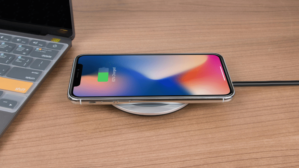
Image courtesy – pexels.com
Safety Features in Wireless Charging
Wireless charging is not just about ease—it’s also about safe operation. Modern wireless systems include several important safety features to protect both the device and the user.
One key feature is Foreign Object Detection (FOD). If a metal object like a coin or key is placed on the charger, it will stop charging to prevent overheating or fire. Many systems also include thermal sensors to monitor temperature in real time. If the device or charger gets too hot, power is reduced or cut off automatically. Additionally, over-voltage and over-current protection are standard features. These prevent spikes in power from damaging the internal electronics of your device.
Together, these safety measures make wireless charging both reliable and secure for everyday use.
Real-World Applications
Wireless charging started with smartphones, but it’s now spreading across multiple industries. The technology is being adopted in everything from vehicles to healthcare.
One major area of growth is electric vehicles (EVs). Brands like BMW and Hyundai are integrating wireless charging pads into their vehicles. These systems use large coils and can deliver power levels up to 11 kW. They are ideal for garages and public stations where drivers can park and charge without plugging in.
In the medical field, wireless charging is a game-changer. Devices like pacemakers and other implants benefit from contactless charging. This eliminates the need for wires passing through the skin, which reduces the risk of infection and increases patient comfort.
Wearables and smartwatches are another perfect match for wireless charging. Their small batteries and low power requirements make them easy to charge using magnetic alignment. That’s why most smartwatches today rely on this method—it’s simple and seamless.
Future of Wireless Charging
Wireless charging is still evolving, and the future looks exciting. Engineers and researchers are working on longer-range charging solutions. Companies like Energous and Ossia are developing systems that can charge devices over the air. This means your phone could charge while sitting in your pocket, as long as you’re within range.
Another innovation is the idea of smart charging surfaces. Tables, desks, and even car dashboards are being designed with built-in wireless zones. You could simply place your phone or laptop anywhere on the surface, and it would start charging automatically.

In the world of electronics and communication systems, phase-locked loops play a key role. From wireless communication to clock signal production and radio tuning, the phase-locked loop hides in the background all around us. It is perhaps one of the most important control systems employed in modern electronics. It is one of the most important control systems in modern electronics. This article will break down the concept, components, types, applications, and some exciting projects and research related to phase-locked loops. Let’s dive in.
What is a Phase-Locked Loop?
A phase-locked loop (PLL) is a control system that compares the phase of two signals. It tries to match the phase and frequency of a generated signal to a reference signal. Once locked, the system keeps the signals aligned. PLLs are used to stabilize frequencies, recover signals, and generate clean clock pulses.
In simple words, a PLL helps in synchronizing one signal with another.
Basic Components of a PLL

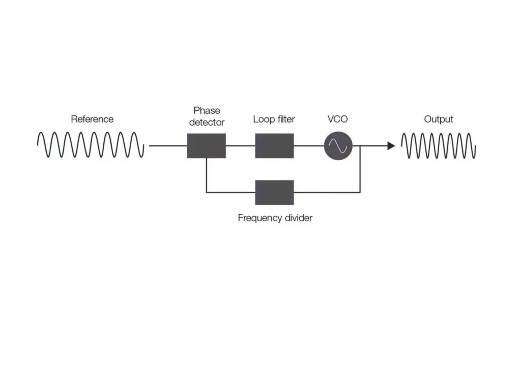
A typical phase-locked loop has three main parts:
Phase Detector (PD)
- Compares the phase of input and output signals.
- Outputs a signal based on the phase difference.
Low Pass Filter (LPF)
- Smooths the output of the phase detector.
- Removes unwanted high-frequency noise.
Voltage-Controlled Oscillator (VCO)
- Generates a signal whose frequency changes based on input voltage.
- This signal is fed back and compared again in the loop.
A Phase-Locked Loop (PLL) works by continuously comparing the input signal with the output of the Voltage-Controlled Oscillator (VCO) using a phase detector. If there is a difference in phase or frequency between the two signals, the phase detector produces an error signal. This signal is then passed through a low-pass filter, which removes high-frequency noise and smooths the output. The filtered signal is used to control the VCO, adjusting its frequency to reduce the phase difference. This process continues in a loop until the VCO output matches the phase and frequency of the input signal. Once synchronized, the system maintains this alignment, a condition known as the lock-in state.
Types of Phase-Locked Loops
There are several types of Phase-Locked Loops (PLLs), each suited for different designs and applications. Analog PLLs (APLLs) are built using analog components and are commonly found in older electronic systems. Digital PLLs (DPLLs), on the other hand, operate with digital signals and are widely used in modern microprocessors and communication devices. A more advanced version is the All-Digital PLL (ADPLL), which is fully digital, offering high speed and flexibility for integrated systems. Another popular type is the Charge-Pump PLL (CP-PLL), which uses a charge pump for better control and precision. CP-PLLs are often used in RF systems and frequency synthesizers where stable and accurate signal generation is critical.
PLL Projects for Engineering Students
PLL-Based FM Demodulator
The PLL-Based FM Demodulator project is based on improving a Phase-Locked Loop to effectively demodulate frequency-modulated (FM) signals. A PLL is a feedback system that locks the phase of a Voltage-Controlled Oscillator (VCO) to the phase of an incoming signal. In this project, the FM signal is fed into the PLL, where the phase detector compares it with the VCO output. Any phase or frequency difference generates an error voltage, which is filtered through a low-pass filter. This filtered output voltage represents the original modulating signal (such as audio or data) that was used to generate the FM signal.
The system consists of a Phase Detector, a Low-Pass Filter, and a VCO. As the FM signal’s frequency varies according to the information it carries, the VCO continuously adjusts to track these variations. The error signal generated due to this frequency deviation effectively reproduces the original signal. This type of demodulation is highly stable, precise, and noise-resistant compared to traditional methods. Applications of PLL-based FM demodulators include FM radio receivers, wireless communication systems, and signal tracking modules, making it a valuable and practical topic for study and real-world implementation.
Clock Multiplier Circuit
A Clock Multiplier Circuit is a digital circuit that generates a faster clock signal from a reference clock of a lower frequency. This is normally achieved using a Phase-Locked Loop (PLL). The idea is to “multiply” the input clock rate by a known ratio to generate a more rapid clock output. Inside the PLL, a Voltage-Controlled Oscillator (VCO) generates a high-frequency signal, which is subsequently divided down by a feedback divider. The PLL regulates the VCO to have the divided signal as in-phase and frequency equal to the reference clock input. By using the right divider ratio, the VCO frequency output can be programmed into a multiple of the input clock and therefore offer a clock multiplier.
Clock multipliers have extensive use in digital electronics, especially in microprocessors, FPGAs, and communications systems, where internal devices operate at greater speeds than the external clocks. For instance, a CPU is provided with a 100 MHz clock by the motherboard but uses a clock multiplier to run the internal logic at 2 GHz. Such circuits help provide high performance while keeping the external systems, which are slower, in synchronization. The stability and accuracy of PLL-based clock multipliers make them a fundamental block in modern high-speed digital design.
PLL-Based Motor Speed Controller
A PLL-Based Motor Speed Controller is a control system using a Phase-Locked Loop (PLL) to precisely track and maintain the rotation speed of a motor. The actual speed of the motor is usually detected by a feedback device such as an encoder or tachometer, which generates pulses proportional to the rotation of the motor. These pulses act as the feedback signal and are compared with a reference frequency (target speed) in the phase detector of the PLL. An error signal is filtered and fed to the input voltage or control signal of the motor so that the system will lock the motor speed concerning the desired reference frequency.
It is extremely good at maintaining constant speed in response to varying load conditions and finds application in situations where accuracy and stability are crucial, such as in robotics, CNC machines, and industrial automation systems. The PLL dynamically compensates the control signal so that any speed deviation is continuously compensated by it, and the reference and actual speeds are locked together very tightly. Compared to traditional open-loop control, a PLL-based speed controller offers better accuracy, faster disturbance response speed, and automatic drift correction, and is therefore a stable and reliable choice for closed-loop motor control systems.
Ongoing Research on PLL
Research on phase-locked loops (PLLs) is active to present, with several exciting areas of development. One key focus is on designing low-power PLLs for mobile and IoT devices, where energy efficiency is crucial. High-speed All-Digital PLLs (ADPLLs) for next-generation technologies like 5G and next-gen processors are another. Researchers are also creating noise reduction techniques to improve the accuracy of signals and improve phase noise models of integrated PLLs used in precision timing systems. The trend is towards more use of software-defined PLLs, where the control logic is established by software instead of hardware. It is more flexible and can be reconfigured easily for various applications.
The phase-locked loop may seem simple, but it powers some of the most advanced technologies today. From your smartphone to satellites, from robots to routers — PLLs keep things in sync. For students and engineers, learning PLL is a smart step. It connects analog, digital, and RF domains. It also opens doors to exciting careers in engineering, control systems, and electronics design. So go ahead, pick a project or explore a new PLL IC. Understanding the phase-locked loop today will help you build better systems tomorrow


-

 Industry Insights9 months ago
Electrical engineering career paths in 2025
-

 Tech Reviews10 months ago
Top 5 Laptops for an Engineering Student
-

 Tech News10 months ago
What Happened to the Chat GPT? – Chat GPT Currently Down!
-

 Tech Reviews10 months ago
5 Cool Tech Gifts for this Christmas Season 2024
-

 Tech News2 months ago
Samsung Unveils Game-Changing Micro RGB TV
-

 Tech News8 months ago
Why DeepSeek is Making Tech Giants Nervous
-

 Tech News7 months ago
Google is bringing lock screen widgets to Android 16 in this year
-

 How-To Guides6 months ago
How Power Factor Correction Capacitors Improve Energy Efficiency